|


|
 |
|


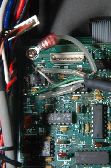
| Here are the power leads for the sampler module. There is a green wire connected to R5. A white wire connected to R9. Then there are red and black wires with a resistor inline stuffed inside a clear tube. The last connection is the ground wire, with a clear tube isolating it from the rest of the board, secured to a phillips head screw. | 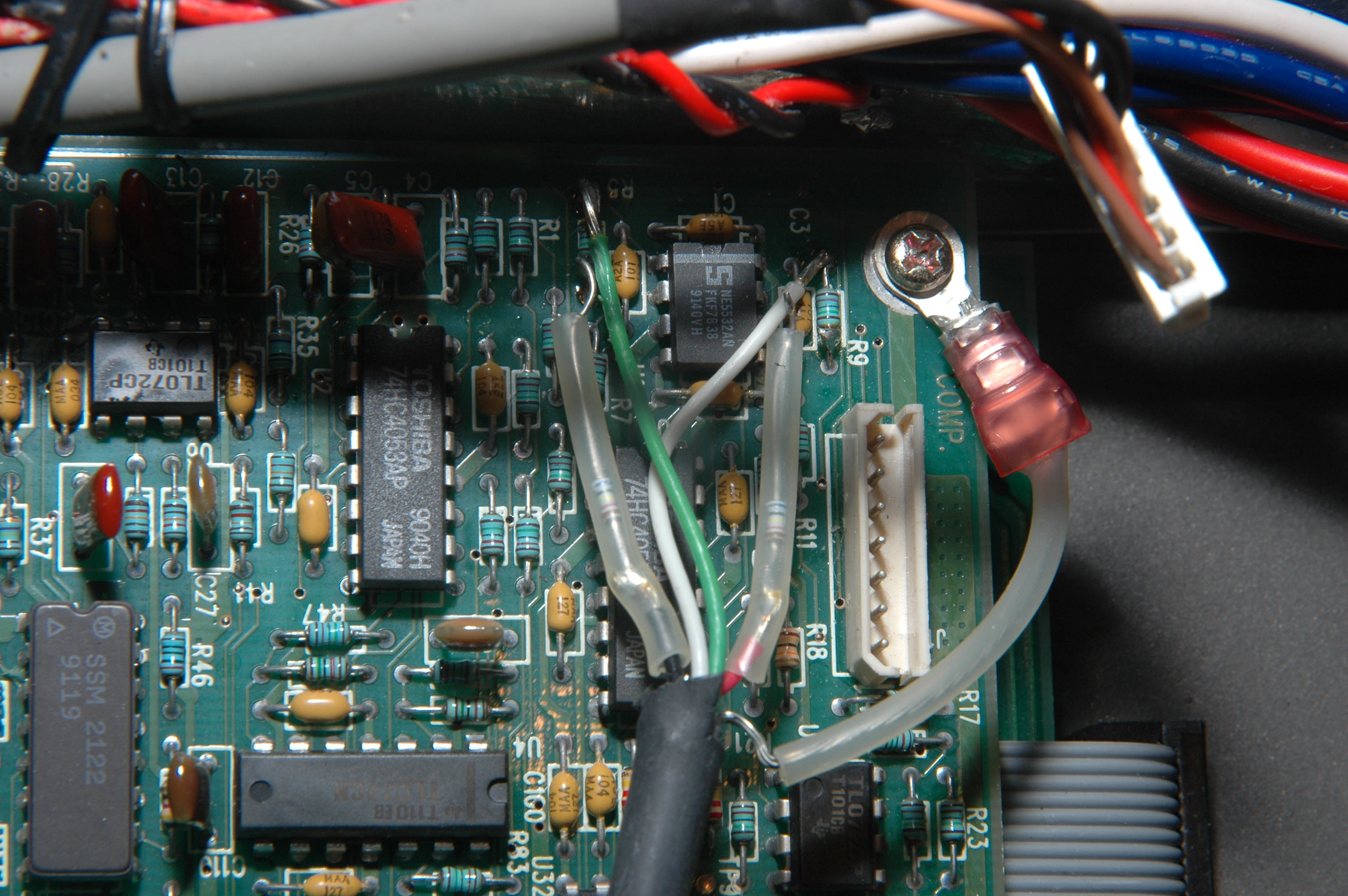 Original Image Original Image |
| Total images: 39 | Help | |